Design
Record of our design process.
Our design process began in early September of 2020 and was focused entirely on solving our problem definition. Most of our overall design decisions were finalized by the end of September, but we continued to tweak the design as new discoveries were made.
Initial Design
In the initial documentation provided to us, our client outlined several suggestions on how to approach this project. They suggested the using Minecraft or Minetest as the platform for hosting our software. We could then use MCreator or the Minetest Lua API for programming the mod. Our client also noted that we should not attempt to write our own power flow simulation software and should instead use other software libraries for this task. This design consideration was critical as realistic and accurate simulation was a primary goal of this project. Our client had experience with an electrical power distribution system simulator called OpenDSS and suggested we look into using this together with DSS Python or some other API interface. We would then make calls to the interface from the mod to OpenDSS to perform power flow simulations and update the game state appropriately. This left us with an initial development stack shown in the image.
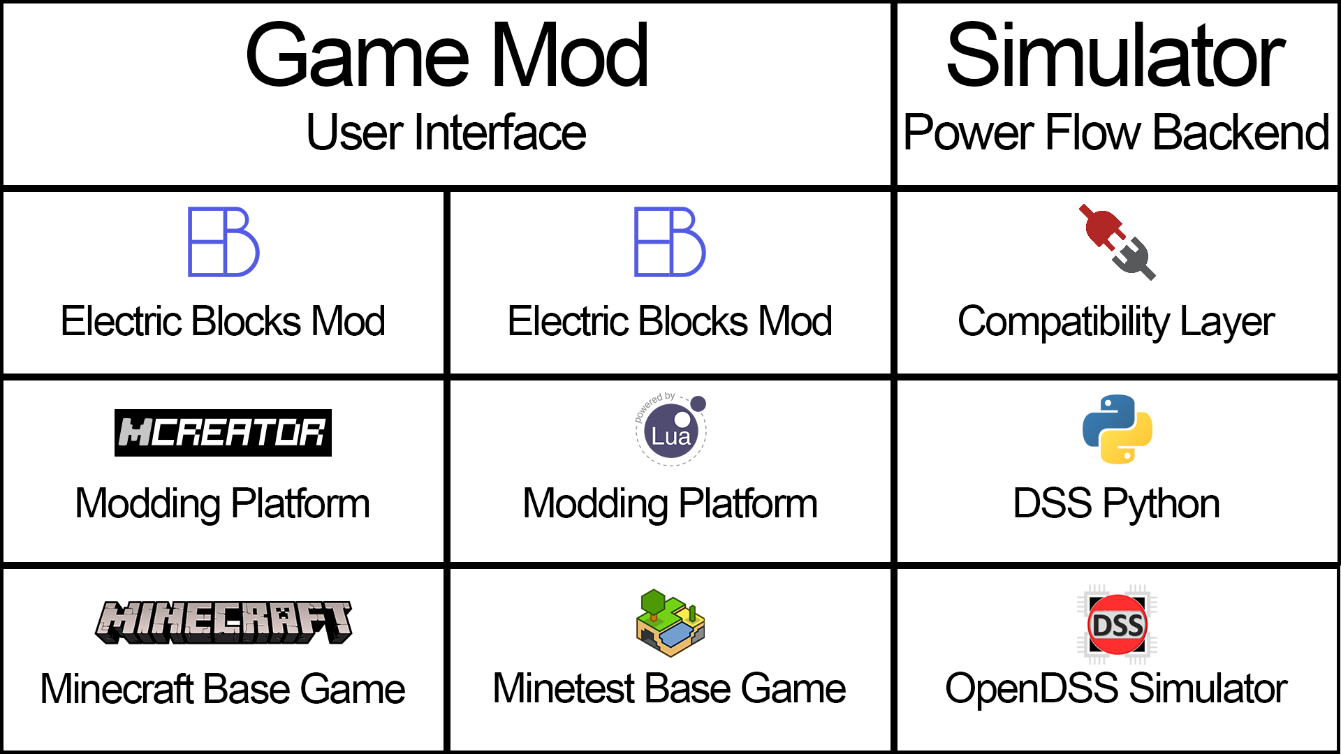
We could choose to design our mod using Minecraft or Minetest. We would then use their corresponding mod creation tools to add blocks into the game based on power engineering elements such as lines, loads, transformers, generators, etc. We would then use information from the game to make calls to OpenDSS using a compatibility layer. OpenDSS would then run a power flow study and return the results to our mod. Finally, the Electric Blocks Mod would use those results to inform the player and modify the game state.
While this design seemed like a good overall solution, we quickly realized that we had a lot of issues that we would need to resolve before proceeding. Should we use Minecraft or Minetest as the basis for our mod? How would our mod communicate with the simulator and is a compatibility layer needed to facilitate communication? How would this architecture work in singleplayer versus multiplayer settings? How would the mod translate the game state into a form that the simulator could understand? These are all questions that we had to do in-depth research on before we could arrive at a final design.
Project Learning
While our initial design plan was solid, we still had many issues that we needed to research before moving forward.
Should we use Minecraft or Minetest as the base game for our project?
These were the two possibilities presented to us by our client. Both our team and client agreed that the block based virtual worlds of Minecraft and Minetest were an ideal sandbox environment for us to use as the basis for our mod, but which one should we use? Minecraft is substantially more popular and has an installation process that is familiar to many players. However, Minetest was designed from the ground up to support mods which provides several benefits. The Minetest Lua API is thoroughly documented and easy to use. Mods are contained and ran exclusively on the server side with code and media being automatically transferred to the client upon connection. This means that the programmer doesn’t have to worry about writing code for both the client and server side in Minetest and players don’t have to take any steps to use the mod if they can connect to a server running it. The benefits of Minetest are substantial, but we ultimately decided to target Minecraft as our base game instead. The target audience for this software is educators/students and engineers. This audience is largely already familiar with Minecraft and how to mod the game. If we went with Minetest, nearly anyone who wanted to use it would need to install this new piece of software. By choosing Minecraft, there would be more programming work involved, but we would be taking advantage of the knowledge, intuition, comfort, and excitement that many people have regarding Minecraft.
What modding platform should we use to develop the mod?
The initial documentation provided by our client suggested that we use a development environment called MCreator to develop the mod. MCreator is designed to simplify the development process and make mod creation easy. While this seems like an appealing tool, further research made us decide against using it. MCreator is a closed system that simplifies code and prevents you from directly accessing Minecraft. While it does make the mod creation process easier, this tool seems to be best suited for individuals who are learning software development and not for those who are creating complex mods. MCreator is actually based on Forge which is the defacto standard modding platform for Minecraft and so that is what we decided to use. Forge hooks into Minecraft and provides us access to the game and an API for modifying game behavior.
How would our mod communicate with the simulator and is a compatibility layer needed to facilitate communication?
Our client initially suggested that we use DSS Python to access API bindings for OpenDSS and that we could use shared files for communication. We quickly ran into issues with using this approach. While DSS Python is cross-platform compatible, it requires that you have the OpenDSS COM interface file compiled to target your specific operating system. OpenDSS is built for Windows and only unofficial builds are available for other platforms. OpenDSS is not cross-platform compatible. This makes installation more difficult and would require us to write platform specific code for interfacing with OpenDSS. We are using Java to write the mod and OpenDSS does not offer a Java binding. Additionally, the OpenDSS COM interface doesn’t provide any functionality for building a power network and requires that you provide it with a file in the form of a DSS script. All these issues meant that using OpenDSS for simulations was not practical for us or our users. Our team concluded that we would need to use some other software for running the simulations and that we would likely need to develop some sort of compatibility layer which allows our mod to communicate with the simulation software. The exact way out mod communicated with the simulator would be dependent on which simulation software we ended up using.
Which power flow simulation software should we use instead?
Since we decided that OpenDSS wasn’t a good fit for our project, we scrambled to find a replacement. We realized that our replacement simulator had to meet several fairly stringent requirements to be useful for our project. Whatever we chose had to be:
- Compatible with all major operating systems (Windows, Mac OS, Linux, etc)
- Easy to install
- Completely free and open source
- Able to run asymmetric three phase power flow
This meant that we couldn’t use any common commercial software offerings. We concluded that PandaPower was the best software to fit our needs.
Final Design
We utilized knowledge gained during research to refine our initial design and create a final design architecture.
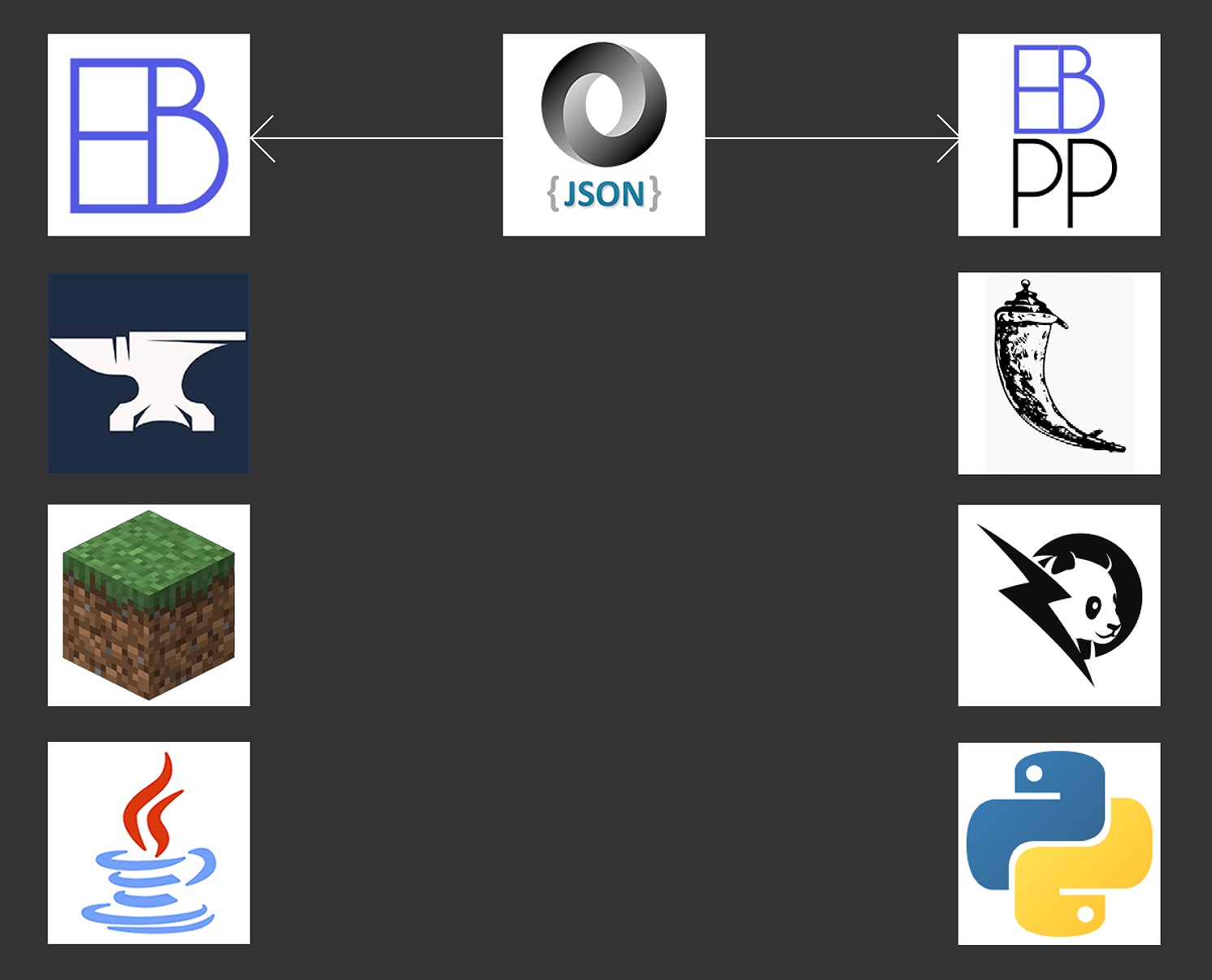
First, we will focus on the left hand side of the technology stack. At the very bottom left we use Minecraft running on Java to host our modification.
We used the Forge modding API to interface with the game. Forge performs a series of modifications to Minecraft base game to assist in compatibility between mods and make modding easier. This gives us access to any information we might need about the Minecraft world. It additionally allows us to easily change the game state as needed.
Our Minecraft modification “Electric Blocks” sits at the top of this stack and is responsible for rendering the user interface, allowing users to construct electrical systems, requesting that simulations be performed on these electrical systems, and updating the in game state to reflect the results of the simulation.
Second, we will focus on the right hand side of the technology stack. At the very bottom right, you can see the icons for PandaPower and Python. PandaPower is the validated library that performs the actual simulation. As we mentioned previously, this is a very important core requirement of our system. We need our results to be usable for real world education and engineering purposes.
Above PandaPower is the logo for Flask. PandaPower works great for running the simulation, but we need a method of communication between PandaPower and the Electric Blocks mod. This is where Flask comes in. Flask is a micro web framework written in Python. It is classified as a microframework because it does not require particular tools or libraries. It has no database abstraction layer, form validation, or any other components where pre-existing third-party libraries provide common functions. On startup it binds to a port (defaults to 1127) and starts listening for HTTP requests. When an HTTP request is detected, it parses the incoming request and makes that information available for processing. This is where our software comes in.
At the top right of the technology stack you can see the logo for Electric Blocks Panda Power (EBPP). EBPP functions are called by Flask when a request is made. EBPP checks to ensure the packet is properly formed and then uses information contained within it to call PandaPower functions to construct a network for simulation. Once the network is constructed, a power flow study is ran on that network. EBPP then extracts the results from PandaPower and converts them into an easily readable form for the Electric Blocks mod. This contains all of the information needed to update the in game state.
All communication between Electric Blocks and EBPP is done using JSON formatting and conforms to a standard set of communication protocols. These communication protocols ensure that the mod and simulation are able to quickly and easily translate requests. This stack allows for many benefits as discussed in the project learning section.
EBPP Network Communication Protocol
The EBPP Network Communication Protocol defines the standards for communication between the Electric Blocks mod and the EBPP simulation server. All requests must be in JSON format and must include a status key that contains the request type. All documentation assumes well formed requests. Any modifications to requests may result in undefined behavior.
Keep Alive
A status of KEEP_ALIVE checks if the server exists and is responding to requests. This is a fairly simple way of validating that the endpoint being accessed is in fact an EBPP server and not some other server. Any other keys and fields other than status are ignored here.
{
    "status": "KEEP_ALIVE"
}
A successful keep alive request will be met with the following response:
{
    "status": "KEEP_ALIVE",
    "response": "Keep alive request acknowledged"
}
Simulation Request
A status of SIM_REQUEST is the primary request for this server and the server will attempt to perform the simulation. Properties for each element will depend on the type, but all keys will be extracted and passed to PandaPower so care should be taken to ensure that you don’t pass any invalid values.
The 3phase key indicates whether any three phase elements are present in this network. At the time of writing, this feature has not been implemented and setting this to true will result in undefined behavior.
The elements key should contain a dictionary mapping an elements unique identifier to it’s corresponding information. Each element in the element dictionary must have a unique identifier of some kind attached to it to ensure proper extraction of results. This can be any string and we use UUIDs for this purpose, but theres no reason you couldn’t use a simple integer counter or anything else. Every single element in this dictionary should contain the etype key which should correspond to the short name of the element being added. Every element has some required fields which are defined in the PandaPower API. All other fields will be passed as optional parameters.
A simulation request will look something like this:
{
    "status": "SIM_REQUEST",
    "3phase": false,
    "elements": {
        "UUID": {
            "etype": "gen",
            "bus": "UUID of Bus",
            "p_mw": 1.0,
            "vm_pu": 120,
            "other_properties": "value",
            ...
        },
        ...
    }
}
EBPP will parse the request, construct the network using PandaPower API calls, run the simulation, and return the results. There are several possible statuses, but we will start by assuming the simulation was successful.
In the event of a successful simulation, the server will reply with a status of SIM_RESULT. Like the simulation request, the results will be held in a dictionary of elements. The unique identifier and etype of each element will match the request and will now contain the result values. The results that are reported are entirely dependent on the PandaPower API and will vary depending on the element type.
A successful simulation result will look something like this:
{
    "status": "SIM_RESULT",
    "elements": {
        "UUID": {
            "etype": "gen",
            "p_mw": 1.0,
            "vm_pu": 120.0,
            "other_results": "value",
            ...
        },
        ...
    }
}
And finally this is an example of a successful simulation request taken right from the Electric Blocks mod. This is a very simple network just containing an external grid connected to a load.
{
  "status": "SIM_REQUEST",
  "3phase": false,
  "elements": {
    "f3ac0bc2-47a5-4527-996e-cd95ed553cae": {
      "etype": "bus",
      "vn_kv": 20
    },
    "f48bac4b-3aa4-45f4-947d-6c7646cce465": {
      "etype": "load",
      "in_service": true,
      "bus": "f3ac0bc2-47a5-4527-996e-cd95ed553cae",
      "p_mw": 0.00006
    },
    "f3a62d80-d93a-4d4e-a176-676487c9cc35": {
      "etype": "bus",
      "vn_kv": 20
    },
    "a65b5154-b7a8-4184-a802-4eaaa09be0f4": {
      "etype": "ext_grid",
      "in_service": true,
      "bus": "f3a62d80-d93a-4d4e-a176-676487c9cc35",
      "vm_pu": 1
    },
    "a929dc54-a867-4d85-aae3-3d14c84a4332": {
      "etype": "line",
      "from_bus": "f3ac0bc2-47a5-4527-996e-cd95ed553cae",
      "to_bus": "f3a62d80-d93a-4d4e-a176-676487c9cc35",
      "length_km": 0.007,
      "std_type": "NAYY 4x50 SE"
    }
  }
}
And the resulting response:
{
  "status": "SIM_RESULT",
  "elements": {
    "f3ac0bc2-47a5-4527-996e-cd95ed553cae": {
      "etype": "bus",
      "vm_pu": 0.999999999460057,
      "va_degree": -6.444894654701214e-8,
      "p_mw": 0.00006,
      "q_mvar": 0
    },
    "f48bac4b-3aa4-45f4-947d-6c7646cce465": {
      "etype": "load",
      "p_mw": 0.00006,
      "q_mvar": 0
    },
    "f3a62d80-d93a-4d4e-a176-676487c9cc35": {
      "etype": "bus",
      "vm_pu": 1,
      "va_degree": 0,
      "p_mw": -0.00006000000003239657,
      "q_mvar": 0.00018472564618222633
    },
    "a65b5154-b7a8-4184-a802-4eaaa09be0f4": {
      "etype": "ext_grid",
      "p_mw": 0.00006000000003239657,
      "q_mvar": -0.00018472564618222633
    },
    "a929dc54-a867-4d85-aae3-3d14c84a4332": {
      "etype": "line",
      "p_from_mw": -0.000059999991175918325,
      "q_from_mvar": 6.749076907549577e-14,
      "p_to_mw": 0.000059999991208314896,
      "q_to_mvar": -0.0001847256462497171,
      "pl_mw": 3.2396570777588896e-14,
      "ql_mvar": -0.00018472564618222633,
      "i_from_ka": 0.0000017320505537747895,
      "i_to_ka": 0.0000056068086085411585,
      "i_ka": 0.0000056068086085411585,
      "vm_from_pu": 0.999999999460057,
      "va_from_degree": -6.444894654701214e-8,
      "vm_to_pu": 1,
      "va_to_degree": 0,
      "loading_percent": 0.003948456766578281
    }
  }
}
Hopefully this should give you an idea of how this works!
General Request Errors
A proper request should result in the expected response, however, there are other possible values that status could be if there is an error of some sort. Those will be covered in this section.
JSON Error
If the body of the request could not be parsed as JSON, the status will be JSON_ERROR. In this case, the following response is sent:
{
    "status": "JSON_ERROR",
    "response": "Some Error Message"
}
Invalid Error
If the body of the request was able to be parsed as JSON, but an invalid status was given or there is some other issue with the request, the status will be INVALID_ERROR. In this case, the following response will be sent:
{
    "status": "INVALID_ERROR",
    "response": "Some Error Message"
}
Simulation Request Errors
When running a simulation request, in addition to the general errors, there are other possible error values that status could be. Those will be covered in this section.
PandaPower Error
This occurs when the simulation request was accepted by EBPP, but calls to PandaPower resulted in an error status of PP_ERROR. This is usually thrown when someone tries to run a simulation without a slack bus, but could also arise from a bug in PandaPower, a bug in EBPP, or the entering of 0 or null values in places where they shouldn’t be. More details about the error are contained in the response. In this case the response will look like this:
{
    "status": "PP_ERROR",
    "response": "Some Error Message"
}
Convergence Error
The clients simulation request was accepted by EBPP and PandaPower didn’t run into any errors when constructing the network, but the simulation was unable to converge on a stable result. In this case, the status will be CONV_ERROR. A network can fail to converge on a solution for a wide variety of reasons. We are planning to integrate the possibility of running diagnostic reports when this occurs, but as of right now the response will just be this:
{
    "status": "CONV_ERROR",
    "response": "Some Error Message"
}
Mod Design
One of the major issues that we had to consider as part of our design process was how our mod was going to track and process simulation networks built in game.
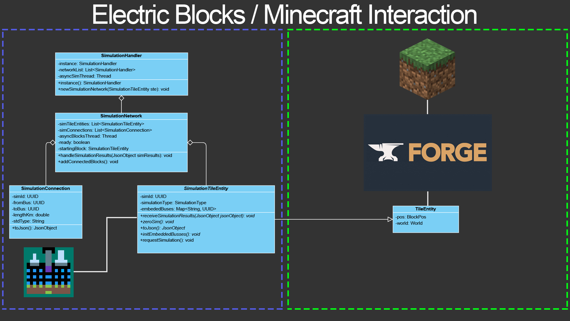
The UML diagram shows the architecture for how this information was stored and processed. We are going to start with the simplest concepts and work our way up.
On the right hand side of the diagram, we have the Minecraft world which is exposed by the Forge API. The game stores information about which blocks are in each location in the game. Simple blocks like stone have no unique information so to preserve memory no objects are created representing them. Intermediate blocks like Cake blocks which only have a finite amount of possible states can use “block states” to encode information like which direction the block is facing. More complex blocks like chests and furnaces, on the other hand, have more complex storage requirements. These blocks need to be able to store information such as which items are stored inside of it. For blocks like these, the possible states are nearly infinite. To allow for this, Minecraft uses a concept called “tile entities”. Tile entities are “attached” to a block and are used for storing additional information and code needed for complex blocks.
Our mod uses this “tile entity” concept for tracking information about elements in the electrical network. We created an abstract class called “SimulationTileEntity” which extends the “TileEntity” class. This class contains information such as a unique simulation identification number (UUID), what simulation type the element is, and what embedded buses the block has. It also provides an interface for receiving simulation results, converting the element to a JSON representation, and other important helper functions. This SimulationTileEntity is not actually instantiated, but is extended by each element so that they can store relevant information. Each element has a subclass of “SimulationTileEntity” attached to it and this creates a common interface for all electrical elements.
Whenever an electrical element is updated, a new “SimulationNetwork” is created with the updated element marked as the starting block. Simulation networks represent a collection of electrical elements connected by wires. The simulation network has functions for identifying connected blocks. This is done asynchronously in another thread to minimize impact on gameplay. Once the network has been fully constructed, it is marked as ready and it can be used to make requests.
All simulation networks are managed by a singleton class called “SimulationHandler”. The simulation handler contains a list of all networks that need to be simulated. All simulations are handled in order to ensure that each successive change to a network is updated in the correct order. The simulation handler class contains all the code and logic used for communicating with EBPP. Whenever a new simulation needs to be created, the tile entity that was affected can call on the simulation handler singleton to create a new simulation network instance with that calling block as the starting point. Once the simulation network has completed building and is marked as ready, the simulation handler constructs a json representation of the network and sends a request over to EBPP for processing. Once EBPP has returned a response, the simulation handler calls the simulation networks update functions with the results which in turn calls each individual simulation tile entities update functions to pass the results to each element in the network. This carefully orchestrated interaction is what allows our mod to function.
Identifying Networks
Our previous diagram explains how simulation networks are managed, but now we will describe how the networks are actually built.
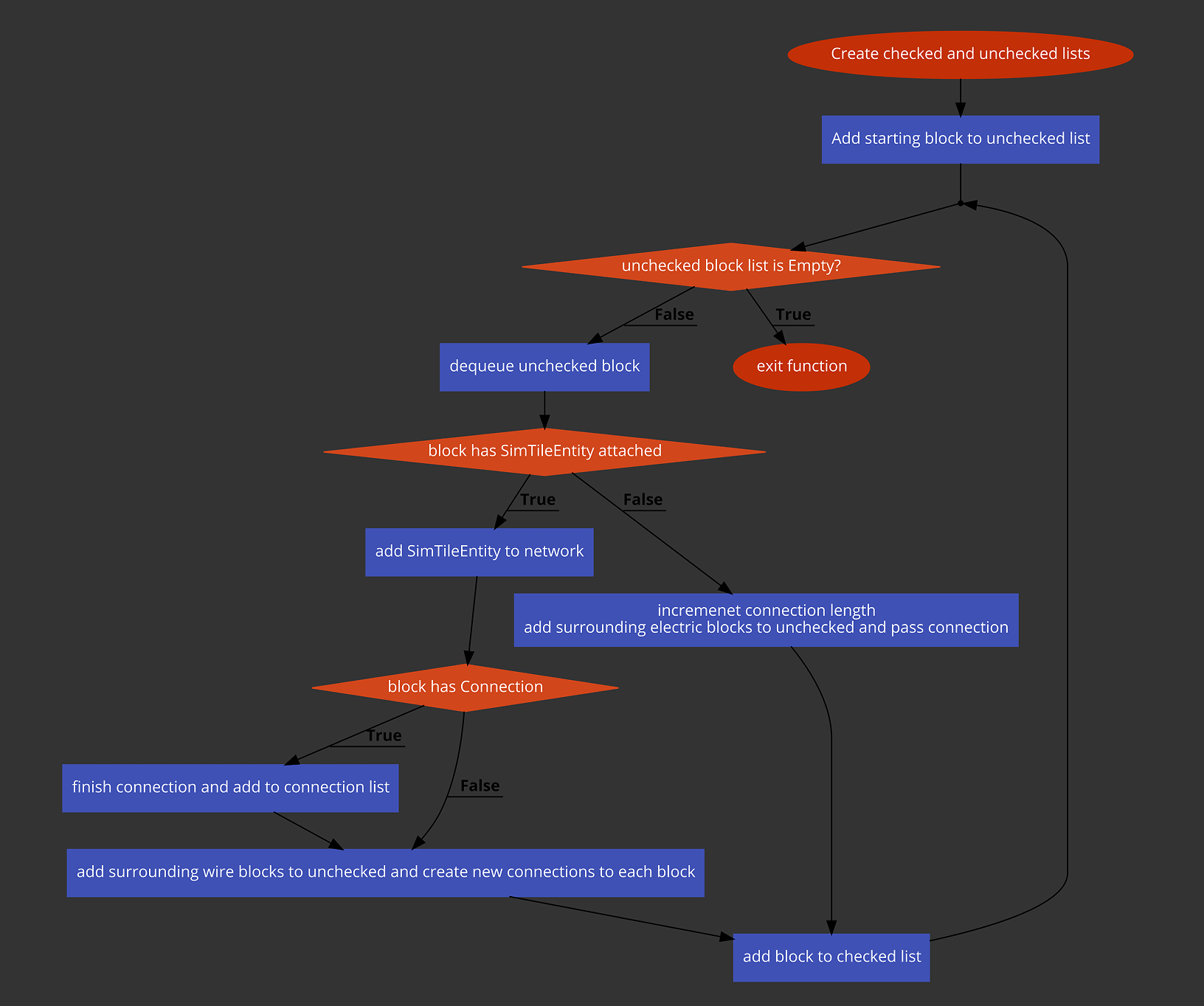
This was another major design challenge that we had to solve. The network building diagram shows a flow chart for how this process works.
Every simulation network starts at some electrical element. This element is marked as the starting block and it has no connections attached to it. Two separate queues are initialized one for checked blocks and one for unchecked blocks. The starting element is added to the unchecked list and then the algorithm starts running.
First we check if the unchecked blocks list is empty. If it is, we can mark this network as built and ready for simulation, but if not we dequeue the first block in the unchecked list. We then check if the block is already in the checked list (not indicated in diagram) and if it is we skip it. We then check if the block has an instance of “SimulationTileEntity” attached. This lets us determine whether or not the block is an electrical element. Wires are not considered electrical elements for this purpose.
If the block does have the tile entity attached then it is added to the simulation network’s list of elements. We then check if the block has an existing connection. If it does then we finish the connection and add the connection to the network. We then add all blocks surrounding the one we are checking (max distance of 1) to the unchecked list and start new connections for them.
If the block does not have a “SimulationTileEntity” attached, then we know the block is a wire so we extend the connection from the previous block and increment the length of the connection. We then add all blocks surrounding the one we are checking to the unchecked list and pass the current connection to those blocks.
The block is then added to the “checked” list and we loop back to the start.
This system resembles a path finding algorithm and it fans out searching for blocks that should be in the network. While this algorithm might seem simple, the actual implementation is fairly complex. Determining which blocks should be in the network is easy, but accurately determining exactly how each block is connected to the other blocks is substantially more difficult. The algorithm in the picture is a dramatically simplified view of what actually happens. To make this actually work, we had to create a private class called “ConnectedBlock” which stores information about the blocks position, current connection, whether or not it has a tile entity attached, and what the previous block was that added this block to the unchecked list. This connected block class maintains an ongoing series of links from the current block all the way back to the original starting block.
GUI Network Communication Protocol
Now that you have a good idea of how things are working, its time to complicate things even more. The original technology stack shown near the beginning of this document was actually a simplified version of what is really going on.
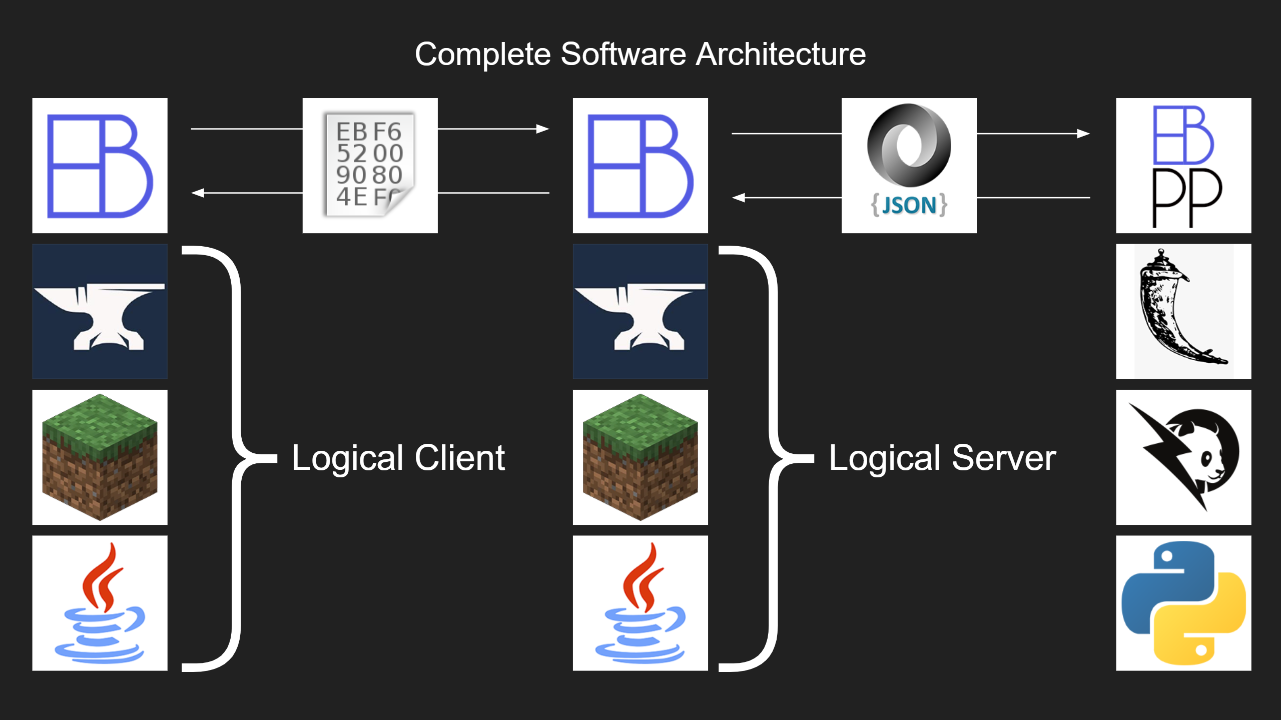
In reality, the Electric Blocks system requires 3 pieces of software running at any one time. Those are:
- Electric Blocks Client Mod
- Electric Blocks Server Mod
- EBPP Simulation Server
To help keep things simple for end users, the client mod and the server mod are packaged into a single “universal” JAR (Java Archive) file. Some code is common to both mods and some is executed only on the client or server side.
You already saw how we synchronize data between the logical server and EBPP, but another challenge we faced in engineering this mod was synchronizing data between the logical client and the logical server. The native Minecraft networking code uses a TCP socket to synchronize data between the client and the server. We were able to easily leverage existing Minecraft code to enable the logical server to send updates to the logical client. Sending updates from the logical client to the logical server was a different story. We weren’t able to utilize native code and had to design another network communication protocol for this purpose. The protocol is defined by the table here:
| Index | # Bytes | Data Type | Variable | Purpose |
|---|---|---|---|---|
| 0 - 3 | 4 | int | x | x coord of updated TE |
| 4 - 7 | 4 | int | y | y coord of updated TE |
| 8 - 11 | 4 | int | z | z coord of updated TE |
| 12 | 1 | boolean | inService | Is TE enabled? |
| 13 - 16 | 4 | int | numInputs | # of inputs to a TE |
| 17 - end | 8 * numInputs | double[] | inputs | Array of TE inputs |
This protocol was necessary for sending updates from the client GUI to the server. Since the data needed to do this was highly regular, we decided to use raw bytes format for maximum speed of encoding and decoding. Any time the user opens up a GUI using the multimeter tool and submit changes, their changes are sent as a packet of raw bytes as described above. This is validated on the server side and a simulation request is performed with the new info. The results of the simulation are then distributed to all connected players. This is what makes multiplayer possible!
Validation
One of the core requirements of the project was that it must model power flow in an accurate and realistic manner. Rather than try to make the simulator on our own, we decided to use the PandaPower library. This library contains undergoes over 250 tests to ensure proper functionality. These tests include automatic validation against industry standard commercial software to ensure the implementation is correct.
Since our software is using a validated simulation system library, our client did not request any validation of our software. We have chosen to validate our software by taking a sample of the test networks used to validate PandaPower and build them in Minecraft. We will then compare results to ensure that the mod is behaving correctly.